BENDING TEST
Material tests are used to determine the properties of a material. These fall into two main categories - destructive testing and non-destructive testing.
Finding Bending Stress and Modulus of Elasticity E
The bending of beams is one of the most important types of stress in engineering. Bending is more likely to be a critical stress than other types of stress - like tension, compression etc.In this laboratory, we will be determining the Modulus of Elasticity E (also called Young's Modulus) of the various materials and using Solid Edge to determine the Second Moment of Area for the different cross-sections.

Bending Equations
Use
units: Force (N), Length (mm), Stress (MPa)
E = Young's Modulus or Mod of Elasticity (MPa)
I = 2nd Moment of Area or Area Moment (mm4). Can calculate using
SolidEdge
sketch.

In our case, we must first convert the mass to Newtons (N). W = kg * 9.81
L is the span length in (mm).
I is the Second Moment of Area in (mm4). We can calculate this for a rectangle using a simple formula;
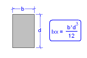
For other
shapes it is not so simple. We need to
calculate these using a CAD program (see footnote).
Determining the value of E in MPa.
From
the above
equation,
Deflection z = W * L3 / (48
* E * I)
so E = W * L3 / (48 * z * I)
Determining Stress in MPa.
From
the above
equation,
Bending Moment (Nmm) M = W*L / 4
and
Maximum Stress (MPa) f = M * y / I
where y = distance from centroid to the bottom (or top) of the beam.
This is
simply half the depth for all the symmetrical beams except the channel.
To find
the centroid for the channel you need to use Solid Edge again (same as
the Ixx
window)
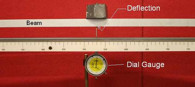
- Load another beam onto the rig.
- Adjust dial gauge to ensure it is touching the beam. Zero the dial face by rotating the lense and locking in place.
- Apply each load and record the deflection measurement.
- Check you have all recordings: Beam material, beam cross-sectional dimensions, span length, deflection readings, masses.
- Make estimates of the errors associated with each measurement. E.g. Parallax error, mis-alignment, mechanical play, incorrect deflections etc
- Repeat for next beam...
Report
- Use Inventor to calculate Ixx
for each beam. While you are still in the profile
sketch (i.e.
before going to a solid)
Ribbon: Inspect tab > Measure panel > Region Properties > Select
the area > Click "Calculate".
> Select
the area > Click "Calculate".
(See more in Footnote) - Ixx is the Second Moment of Area in bending with a vertical load. (i.e. the Neutral axis is horizontal, or the x-x axis)
- Write a short report on the beam bending results. Each beam must have at least 3 weights. Make sure the deflection does not exceed the travel of the dial indicator (if so, use a lighter weight).
- Using the equations above, calculate the value of E. Compare these values to the values obtained from the internet. E.g. Matweb. Show the working for 1 example calculation, but only give the rest of the answers in a table. Use Excel to do your calculations.
- Determine the maximum stress for each mass (load) added to the beams.
- Discuss any sources of error in the experiment - esp measurements - and how they might affect the results. Specify an overall error for your calculation of E.

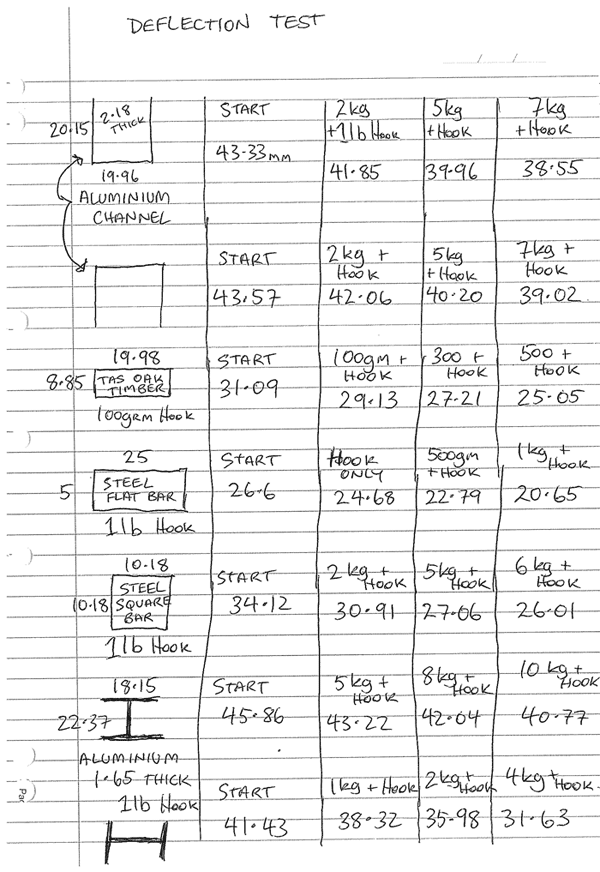
WEDNESDAY RESULTS (Thanks to Darryn Reid)
- Length between supports = 1150mm (Measured with tape measure)
- Masses accurate to +/- 10 grams
- Sydney value for g = 9.76983 (Ivanoff). Assume accurate to 4 decimal places.
| “I” beam. | Mild steel (flat) | Mild steel (square) | Wood | Channel | |
 |
 |
 |
 | 20x20x1.4mm | |
| Mass | Deflection | Deflection | Deflection | Deflection | Deflection |
| kg | mm | mm | mm | mm | mm |
| 0.5 | 0.35 | 2.9 | 0.82 | 6.08 | - |
| 1 | 0.7 | 5.57 | 1.7 | 12.39 | - |
| 1.5 | 1.09 | 8.42 | 2.62 | 17.83 | - |
| 2 | 1.465 | 11.35 | 3.56 | exceeded | - |
Lab 20111017: Monday night class;

20120809 Test results:
Mon 9 Sep 2013
| - | - | 10x10 M/S | alloy "I" Beam | M/S Flat Bar | Timber | alloy chanel |
| grams | deflection | deflection | deflection | deflection | deflection | |
| a | 0 | 0 | 0 | 0 | 0 | 0 |
| b | 457 | 0.45 | 0.35 | 1.85 | 0.75 | 0 |
| c | 959 | 0.95 | 0.65 | 4.15 | 1.6 | 0.6 |
| d | 1464 | 1.5 | 0.83 | 4.95 | 2.45 | 1.1 |
| e | 1921 | 1.79 | 1.15 | 8.05 | 3.5 | 1.4 |
| f | 2467 | 2.7 | 1.35 | 9.9 | 4.2 | 1.9 |
| g | 5457 | na | 2.6 | na | na | 3.5 |
| h | 0 | -0.1 | 0.1 | 0.25 | -0.1 | 0.05 |
Errors (If required by teacher)
(Pre-requisite: Errors test Tester #11104_Errors. See notes on Error Analysis.)
Record
the absolute error for each
measurement: The absolute error is the sum of several factors:
Absolute error = (Resolution / 2) + (Parallax error) + (misalignment
error) + (systmatic error)
Where: Resolution Error = smallest increment in the measurement scale. The human limit is considered to be half of this again. For example, this dial gauge has smallest increment = 0.01mm, so it is considered to be readable to 0.005mm.

Parallax error is an error caused by viewing the meaurement at an angle. Parallax is an apparent displacement or difference of orientation of an object viewed along two different lines of sight. This is why the passenger in a car thinks you are going over the speed limit, but from the driver's view, the needle says the car is going the right speed! Parallax is avoided by looking straight-on, and also kept to a minimum by keeping the needle close to the scale. Your estimate of parallax error depends on the geomtery of the measurement, but for the gauge above the parallax error would be only about 10% of the increment.
Misalignment error: Not taking the measurement parallel or perpendicular. Eg.The dial gauge is not vertical, the tape measure is at an angle, the caliper is not perpendicular etc. This is not supposed to happen if you take the measurement carefully, but some meaurements are more difficult than others.
Systematic error: An error inherent in the measuring instrument itself. Eg a tape measure is inaccurate due to temperature change, or it is actually printed wrong! Hopefully this is not a problem, but the only way top check is to check the calibration against a known standard.
Note:
In 2012 the deflection was measured manually using a dial caliper. This avoids the spring force of the dial indicator changing the deflection of the lighter beams (e.g. wooden beam). It also has greater deflection than the 10mm of the dial indicator.
