THREE FORCE PRINCIPLE
If a body in equilibrium has three forces, they must be concurrent.
Lecture Notes: ![]() 3FP.pdf
3FP.pdf ![]() 3FP.one
3FP.one
| Type | Video Lesson Description and Link | Duration | Date |
| Lecture | |||
| Online | 20200427 | ||
| Online | 5:09 | 20200504 |
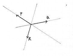
Why three forces must be concurrent.
To ensure equilibrium, there can be no rotation. This can only be achieved if all three forces intersect at one point. On top of that, the forces must add up to give zero resultant.Steps in a typical Three Force problem
Steps in the 3 Force Principle (For some typical questions)1. Isolate the body in question.
2. Locate the points on the body where the 3 forces are applied. (Usually where it touches, gravity through the centre)
3. Determine as many force direction as possible. (Often 2 of the forces have known direction such as gravity (270 degrees), roller force (perpendicular to surface), cable force (along centreline of cable) etc.
4. Locate the intersection, then determine the angle of the 3rd force. (Since it must also go through the same intersection point. You should now have all three angles.
5. Now draw the force polygon.
Remember.
- The point of intersection can be arbitrary (random) - it is not always a joint or a location WHERE forces are applied. It is often out in space somewhere away from the body.
- Make sure you keep the diagrams separate; Space Diagram, FBD and FPolygon. This is very important in these questions because an accurate Picture (Space Diagram) is needed in order to obtain the point of intersection and correct force angles.
In many cases, the point of intersection is arbitrary. It may not even be on the body.
Diagrams
The Space Diagram (SD)
It is usually necessary to sketch accurately, showing dimensions. This must be a scaled drawing.The Free Body Diagram (FBD)
Since forces are concurrent, the Free Body Diagram is a dot, but we still need a SD to determine angles (see step 3 below). See Free Body Diagrams for more information.- Isolate the body.
- Locate contact points (border crossings). There should be three of course
- Line of Action. Back in the Space Diagram, determine the line-of-action of forces using the rules for standard connections (support reactions). Now find the single point of intersection for the three forces. This will give all the angles.
- "To the Body". Identify the direction as applied "to the body".
The Force Polygon (FP)
The force polygon must be drawn strictly to scale, and everything is a Force. The only information coming from the FBD is; Force magnitudes and Force Angles.Since there are three forces, we should have a force triangle. Assuming we know all angles and have unknown lengths this can be solved using CAD, or geometrically using the sine rule. Using the components method you should end up with simultaneous equations which can be solved by substitution.
STEP BY STEP...
The
Sketch (Space
diagram)
1. Identify a body with 3 relevant forces.
2. Get all the information you can. Especially ANGLES. Look for gravity
(270o), special reactions like cables
(Angle=cable angle & tensile), no friction (90o to surface) etc. See table below. (Support Reactions)
3.
You must know the direction of 2 forces. Where these intersect is the
concurrency point. The third force (unknown angle) must also go through
this point.
4. If you drew the relevant details to scale, you now have ALL 3
ANGLES. You have finished the sketch.
The
FBD
1. The FBD is now a dot (treated as a concurrent force
problem).
2. Ensure all forces are in 360 notation
------------------------ ONLY ANGLES ALLOWED PAST THIS POINT
----------------------
The FP
1. Make sure you only copy ANGLES from the FBD. Nothing else!
2. You must know magnitude of at least 1 force (common), maybe
2.
Support Reactions
You will need to determine the angle of some forces in order to find the intersection point.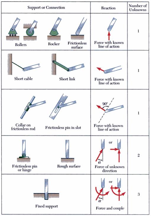
From Vector Mechanics for Engineers: Beer, Johnston, Eisenberg, Staab p165
Worked Example 1
Braced FrameA weight force of 150kN hangs from the end of this beam. The beam is supported by a strut. Note:
|
 |
Scale Drawing (Space Diagram)Draw this diagram accurately to scale.We need to pick a body with three forces (the beam). |
 |
Determine intersection point from the Scale Drawing (Space Diagram)What we know:
Now we know the angle of the 3rd force that goes through the pin joint between the wall and the beam. (pin joints can have force at any angle) |
 |
The FBDWe know all three angles (from the above space diagram).There are 2 unknown magnitudes |
 |
The Force Polygon
|
|
Autocad sample file: strut-example.dwg or strut-example.zip Note: The answer 406.0051kN is based on the vertical length of 1360mm. |
|

Worked Example 2
Lifting a poleA man pulls on a rope to raises a 10 kg pole, of length 4m. Find the tension in the rope and the reaction at A. |
 |
FBD to Scale.The body with 3 forces is the log.We know direction of gravity at G. We know direction of cable force at B. Draw this diagram accurately to scale to get intersection point of these 2 forces, and hence the angle of the 3rd force at A. |
 |
Force Polygon
|
 |
Above illustrations from Vector
Mechanics for Engineers: Statics. 7th ed. Beer, Johnston, Eisenberg,
Staab. McGraw Hill. 2005 (GoogleBooks)
Summary: Equilibrium of Concurrent Forces
So far we have only discussed forces that intersect at one common point (concurrent forces). Sometimes this is not obvious - especially in the case of three forces. For equilibrium of concurrent forces, we must check two things:
- Do the forces intersect at one point? (Concurrent)
- Does the Force Polygon add up to zero resultant (closed loop)?
| Number of forces | FBD (Line of action plan) | Force Polygon (Magnitude plan) | ||
| 2 | Forces must be collinear. Cables, struts, pin jointed members with 2 connections. |
 |
Forces must be "on top of each other" and in opposite directions |  |
| 3 | Forces must intersect at
one point. |
 |
Forces must form a closed triangle |  |
| 4 | Forces must intersect at one point |  |
Forces must form a closed polygon | 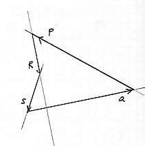 |
From http://www.ecf.toronto.edu/apsc/courses/civ214/Lectures/Equilibrium%20of%20coincident%20forces.html
! Beware of Parallel Forces...
There is one situation when you can have equilibrium, three forces, but they are not concurrent. Parallel forces!For example, in this screw clamp below the wooden jaws are under 3 forces. They are parallel so they cannot intersect. They must still balance of course, or the clamp will not be in equilibrium (which means it must be accelerating). To analyse the wooden jaw, this type of problem falls into the non-concurrent force category which we will study later.


Whiteboard:
Whiteboard
Questions:
Three Force Questions.pdf (Ivanoff old edition)Homework Assignment:
Do questions 4:9 to 4:20. (New book 5:9 to 5:20)
Draw the Space Diagram, Free Body Diagram and Force Polygon for each question.
You can use CAD (recommended for the FBD) and/or Excel. (Or you can do it mathematically by hand if you really want to!).
Note: Excel is not permitted during this test (Tester: Exam mode).